How to Choose C Mount Industrial Lenses in 2026?
Choosing C Mount Industrial Lenses in 2026 requires more than matching a lens thread to a camera. The C-mount standard uses a 1-inch, 32-thread interface and a 17.526-millimeter flange focal distance. However, mechanical compatibility does not guarantee clear images. Sensor size, pixel pitch, working distance, and illumination must work together. A 25-millimeter lens may frame a metal part correctly, yet reveal soft corners on a larger sensor.
Industrial demand is also becoming more demanding. The International Federation of Robotics reported 541,302 industrial robots installed worldwide in 2023 in its World Robotics 2024 report. More robots mean more inspection points, tighter tolerances, and greater pressure on vision systems. The Association for Advancing Automation has also highlighted machine vision as a key technology in automated manufacturing. These trends make resolution, distortion control, contrast, and vibration resistance practical selection criteria, not brochure features.
A reliable evaluation should compare MTF performance, distortion percentage, depth of field, spectral transmission, and compatibility with the camera’s sensor. Check the image circle carefully. Test the lens at the real working distance. Include the intended lighting.
Small details matter.
A lens rated for visible light may perform poorly under near-infrared illumination. A low-cost model can appear sharp at the center but fail near the edges. This is where many selection guides become too confident. Reports describe market direction, but they cannot replace a controlled production test. In this guide, C Mount Industrial Lenses are assessed through measurable specifications, application evidence, and practical limitations. The goal is not the most impressive datasheet. It is a stable image, repeatable inspection, and fewer surprises after installation.
What Is a C-Mount Industrial Lens?
How to Choose C Mount Industrial Lenses in 2026?
What Is a C-Mount Industrial Lens?
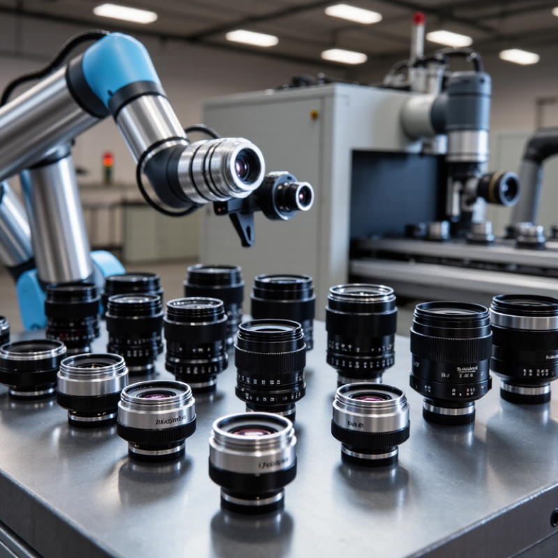
A C-mount industrial lens is a screw-attached optic for cameras used in inspection, measurement, and automation. Its standard thread is 1 inch with 32 threads per inch. The flange focal distance is 17.526 millimeters. That dimension matters. A small mounting error can make a sharp image impossible.
C-mount lenses support different focal lengths, apertures, and sensor formats. Choose the lens by sensor size, working distance, field of view, and required detail. Do not trust the focal length alone. A 16 mm lens may show a wide area, but it can distort edges when the camera sits close. Check the lens image circle against the sensor. Oversight here is common, even in experienced teams.
Demand for reliable vision hardware is growing with automation. The International Federation of Robotics reported 541,302 industrial robots were installed worldwide in 2023. The World Robotics 2024 report links this expansion with broader factory automation needs. Market research from Fortune Business Insights also projects strong growth for machine vision through 2032, although estimates differ by research method. That uncertainty deserves attention.
A practical selection test uses the real camera, lighting, and target. Measure the smallest feature. Leave focus room. Review corner sharpness, reflections, and heat exposure. I once treated resolution as the main priority. The resulting image looked sharp, but glare hid the inspection mark. C-mount selection is technical, yet field conditions often decide success.
Which Specifications Define Lens Compatibility?
Choosing a C-mount industrial lens in 2026 starts with compatibility, not price. The C-mount uses a 1-inch, 32-thread interface and a 17.526 mm flange focal distance. A CS-mount camera usually requires 12.5 mm, so the wrong pairing can prevent infinity focus. A spacer may solve this problem, but it cannot correct poor sensor coverage.
Check the lens image circle against the sensor’s actual diagonal. A 1-inch sensor needs roughly 16 mm coverage, while a 2/3-inch sensor needs about 11 mm. Oversizing the image circle can reduce corner shading, but it may increase cost and physical size. According to the 2024 MarketsandMarkets machine vision report, the global machine vision market was estimated at about 30.8 billion US dollars in 2024, making reliable component matching increasingly important. The number gives market context, not proof of lens quality.
Resolution must match pixel pitch, not only megapixels. EMVA 1288 testing evaluates spatial frequency response, signal-to-noise ratio, quantum efficiency, and dark noise. Ask for MTF data at the required wavelength and field position. Infrared inspection also needs confirmed transmission, because visible-light specifications may become useless near 850 or 940 nanometers. Working distance, aperture, distortion, chief-ray angle, and filter clearance should be checked on the mounted camera. I still verify focus mechanically; a specification sheet can look complete and mislead. Small errors appear first at the corners.
| Specification | Reference Value or Standard | Why It Defines Compatibility | Selection Check |
|---|---|---|---|
| Mount Thread | C mount: 1 inch diameter, 32 threads per inch Thread designation: 1"-32 UN | The mechanical thread must match the camera or an approved mount adapter. | Confirm that the camera uses a C mount, not a CS mount, T-mount, M42 mount, or another interface. |
| Flange Focal Distance | C mount: 17.526 mm CS mount: 12.5 mm | This is the distance from the mounting reference surface to the image sensor plane. It determines whether the lens can focus correctly at infinity. | A C-mount lens generally requires a camera with a 17.526 mm flange focal distance. A 5.026 mm spacer is commonly used when adapting a C-mount lens to a CS-mount camera, subject to clearance and adapter design. |
| Sensor Format Coverage | Common industrial formats: 1/3 inch, 1/2 inch, 2/3 inch, 1 inch, 1.1 inch, and 4/3 inch | The lens image circle must fully cover the active sensor area to avoid dark corners or reduced usable resolution. | Choose a lens format equal to or larger than the sensor format. A larger-rated lens can usually cover a smaller sensor, but may not provide the most efficient field of view. |
| Image Circle | Must be at least as large as the sensor diagonal | Image circle is the diameter of the sharp projected image formed by the lens. | Compare the lens image-circle diameter with the sensor's active diagonal, especially for non-standard or high-resolution sensors. |
| Focal Length | Typical fixed C-mount choices: 4 mm, 6 mm, 8 mm, 12 mm, 16 mm, 25 mm, 35 mm, and 50 mm | Focal length controls the field of view and the working distance required for a given inspection area. | Shorter focal lengths provide wider views; longer focal lengths provide narrower views and greater subject magnification at the same distance. |
| Field of View | Determined by focal length, sensor size, and working distance | A lens may be mechanically compatible but still unsuitable if it cannot capture the required inspection area. | Calculate horizontal field of view approximately as: 2 × working distance × tan(horizontal angle of view ÷ 2). |
| Working Distance | Specified as a fixed distance range or adjustable focusing range | Working distance affects field of view, perspective, lighting space, and whether the lens can focus on the target. | Verify the required distance from the front of the lens to the target, not only the distance from the camera body. |
| Maximum Aperture | Common markings include f/1.4, f/1.8, f/2.8, f/4, and f/5.6 | A smaller f-number allows more light to reach the sensor but generally reduces depth of field and may increase optical aberrations. | Match the aperture range to the available illumination, required motion-free exposure, and acceptable depth of field. |
| Aperture Control | Manual iris, fixed iris, or motorized/automatic iris | The control method affects exposure stability and integration with the camera or machine-vision controller. | For changing illumination, use an adjustable iris; for repeatable fixed lighting, a manual or fixed iris may be sufficient. |
| Focus Control | Manual focus, lockable focus, or motorized focus | Focus adjustment determines whether the target can be resolved at the selected working distance. | Prefer a focus-lock mechanism in applications exposed to vibration or repeated mechanical movement. |
| Resolution Requirement | Specified in line pairs per millimeter, modulation transfer function, or supported pixel size | A lens must resolve enough detail for the sensor and inspection task; nominal megapixel labels alone do not define optical performance. | Check measured resolution across the center and edges of the image at the intended aperture and working distance. |
| Wavelength Range | Visible light is commonly approximately 400–700 nm; near-infrared performance must be specified separately | Glass transmission, focus position, and aberration correction can change with wavelength. | For monochrome, near-infrared, ultraviolet, or multispectral imaging, confirm transmission and chromatic focus performance for the operating band. |
| Spectral Correction | Visible-corrected, near-infrared-corrected, or broadband design | Different wavelengths may focus at different positions unless the lens is designed for chromatic correction. | Use a wavelength-matched lens when switching between visible and near-infrared illumination or when precise focus is required. |
| Distortion | Often expressed as a percentage of image height or field height | Barrel or pincushion distortion changes the geometric position of features and can reduce measurement accuracy. | For dimensional inspection, select a low-distortion lens or apply a validated calibration and distortion-correction process. |
| Telecentricity | Object-space, image-space, or bilateral telecentric design | Telecentric lenses reduce perspective-dependent size changes and are useful for precision measurement. | A conventional C-mount lens is not automatically telecentric. Verify the telecentric specification and required object-space clearance. |
| Back Focus and Sensor Clearance | Back focus must reach the sensor plane without mechanical interference | Filters, protective windows, shutters, and recessed or protruding sensor assemblies can affect focus and clearance. | Check the camera's sensor recess, lens rear protrusion, filter thickness, and any adapter thickness before installation. |
| Filter Compatibility | Front filter thread may be specified in millimeters, such as 25.5 mm, 30.5 mm, or 37 mm | Filter threads determine whether optical filters, protective windows, or polarizers can be installed without vignetting. | Confirm thread diameter, pitch, filter thickness, and whether the filter obstructs the field of view at the selected focal length. |
| Mechanical Envelope | Check lens length, outer diameter, mass, and mounting position | Physical dimensions affect enclosure design, bracket strength, robot clearance, and access to focus or iris rings. | Allow space for connectors, locking rings, protective housings, and thermal expansion in the complete camera assembly. |
| Environmental Rating | Verify the specified operating temperature, humidity, vibration, shock, and ingress protection | Industrial environments may expose the lens to vibration, dust, moisture, oil mist, or temperature cycling. | Choose a lens with documented environmental limits that exceed the actual installation conditions. |
| Lighting and Coating | Anti-reflection coatings and flare-control performance should match the illumination setup | Reflective parts, bright LEDs, and off-axis light can cause ghosting, flare, and contrast loss. | Evaluate the lens with the actual light source, angles, filters, and enclosure rather than relying only on indoor visual testing. |
| Compatibility Decision | Compatible only when mechanical, optical, spectral, and environmental requirements are all satisfied | A matching thread alone does not guarantee a usable imaging system. | Validate the complete camera-lens-lighting combination using the real target, working distance, exposure, and production speed. |
How to Match Lens Features to Imaging Requirements
How to Choose C Mount Industrial Lenses in 2026?
C-mount lens selection should begin with the object and sensor, not price. Define the smallest feature that must be detected. Then calculate the required pixels per millimeter. A 2.3-megapixel sensor may still fail when contrast is weak or lighting changes. Match the lens image circle to the sensor size. Otherwise, corners may darken or lose detail. Focal length depends on working distance and field of view. Short lenses cover more area. Longer lenses show finer details from a greater distance. Check distortion carefully for measurement tasks. Even small barrel distortion can affect edge positions. Aperture also matters. A wider aperture improves brightness but reduces depth of field.
Industry forecasts show why this decision deserves care. MarketsandMarkets’ 2024 report estimates the machine vision market will grow from 13.7 billion dollars in 2024 to 20.6 billion dollars by 2029. IMARC’s 2024 report predicts a different market boundary and projects strong growth through 2032. The estimates differ. That difference reminds engineers to inspect definitions, not repeat impressive numbers. Higher resolution does not automatically produce better inspection results. I still see megapixels valued above optical stability. That choice can be wrong.
Tips: Measure the real working distance, including guards and cables. Test the lens with final lighting, not a bright laboratory lamp. For moving targets, compare shutter speed, aperture, and motion blur together. Record corner sharpness and distortion. A perfect specification sheet can still fail on a warm production line. Recheck focus after temperature changes. Small details matter.
How to Evaluate Working Conditions and Build Quality
Choosing a C mount industrial lens in 2026 starts with the working environment, not the catalog.
Check lighting, temperature, vibration, dust, and available space around the camera. A lens used beside a stamping machine needs stronger mechanical stability than one used on a quiet inspection bench. For bright metal surfaces, test flare and contrast under real production lights. For dark objects, measure low-light performance instead of trusting maximum aperture alone. I have found that a lens can look sharp in a controlled room but lose detail near reflective equipment. That mistake is easy to make.
Build quality deserves hands-on inspection. Turn the focus and aperture rings slowly. They should feel even, without looseness or sudden resistance. Examine the metal barrel, thread accuracy, locking screws, and filter seating. A secure C mount should hold alignment after repeated adjustments. Internal dust protection also matters in dusty workshops. However, no lens is perfectly sealed, and product claims need verification. Ask for temperature ratings, vibration test methods, and sample images from comparable conditions. Short tests can mislead.
Check image stability after heating the camera for several hours. Slight focus drift may appear. It is not always a lens defect; mounting stress can contribute. Use a rigid adapter and confirm the sensor format before purchase. A mismatched image circle can create dark corners. Leave room for error. Reliable selection comes from measured results, not impressive specifications alone.
How to Compare, Install, and Maintain C-Mount Lenses
Choosing a C-mount industrial lens in 2026 requires more than matching focal length. Compare the lens image circle with your sensor size, not just the camera specification. A 25 mm lens may suit a narrow inspection area, while a 12 mm lens captures more of the production line. Check resolution at the sensor edge, distortion, aperture range, and working distance. Bright factory lighting can expose flare and uneven sharpness. Small mistakes matter.
Installation should begin with power removed and both mounting threads inspected. A standard C-mount uses a 1-inch, 32-thread-per-inch connection and a 17.526 mm flange focal distance. Turn the lens gently; never force a cross-threaded mount. Secure the camera, set the working distance, and adjust focus at the actual inspection position. Use a test target with fine lines, because a nearby box may look sharp while critical edges remain blurred. I once trusted the center image too quickly.
Maintenance is simple but not casual. Keep the front and rear caps fitted when the lens is stored. Remove loose dust with clean air, then use approved optical tissue with minimal pressure. Fingerprints can create bright halos around metal edges. Check the locking ring, housing, and cable clearance during routine inspections. Record focus, aperture, and lighting settings after calibration. Recheck them after vibration, temperature changes, or camera replacement. Perfect alignment is rarely permanent.
How to Choose C-Mount Industrial Lenses in 2026?
Compare the approximate active sensor widths below before selecting a C-mount lens. The lens image circle should be at least as large as the sensor diagonal to avoid vignetting.
Installation: Confirm the 1-inch-32 C-mount thread, set the correct back focal distance of 17.526 mm, secure the lens without cross-threading, and focus at the actual working distance. Maintenance: keep the front element capped when unused, remove dust with clean air, use optical tissue with approved cleaner, and periodically check focus-lock and mounting-ring tightness.
Article Source:
Contact us
Please fill out the enquiry form, and our dedicated team will promptly attend to your request